Table of Contents
IO panel
The right side I/O panel are quite different compared to the original VIC 20.
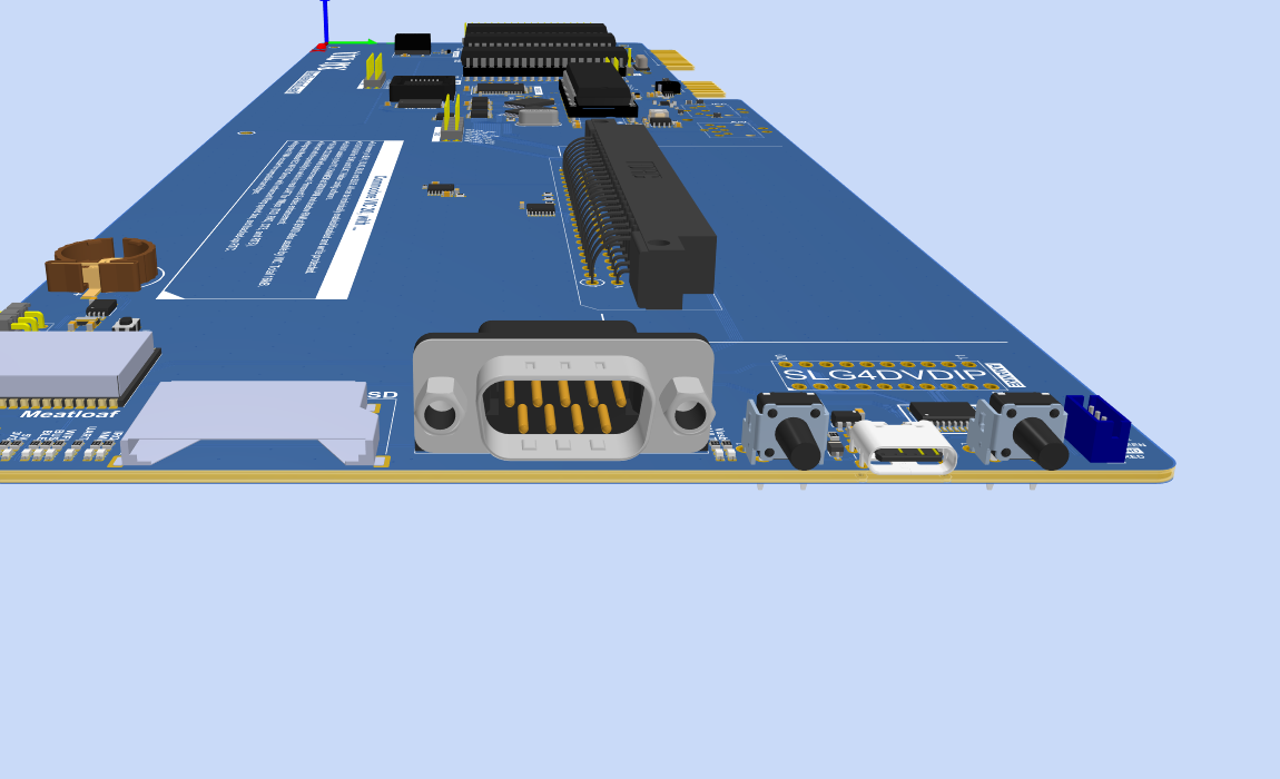
- Furthest to the right we have the RESET button. This does what you expect and reset the whole system including the Meatloaf. A long press on the reset will enter the configuration firmware where you can change settings around using UART, memory mapping, auto loading cartridge images, default font, etc.
- To the left of that we have a USB Type-C connector which is for power input as well as upploading new firmware to Meatloaf and new configuration to the CPLD that handles the memory management. Needs to be able to supply 5V and 3A.
- To the left of that we have another tactile switch. This is the POWER button. A short press turns on the power and a long turns off the power.
- Left of the power button we have the usual 9-pin DSUB connector. This is for your ordinary VIC 20 joystick, paddles and light gun.
- Lastly, and furthest to the left, is the SD card socket. This is connected to the integrated Meatloaf.
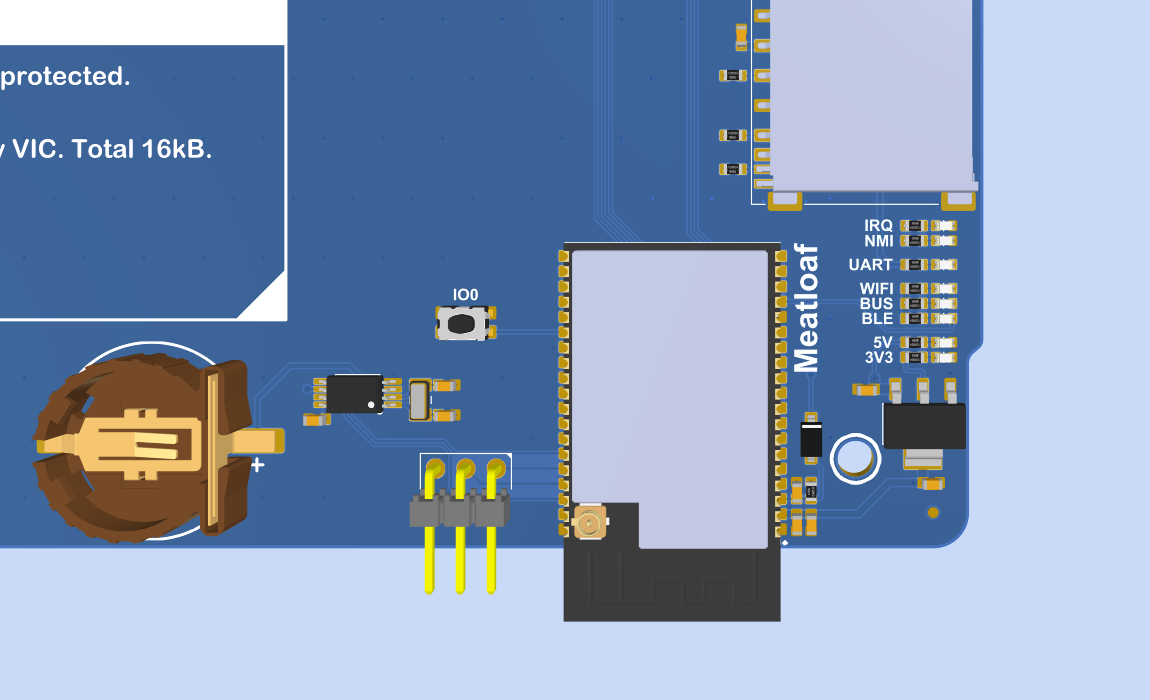
Integrated Meatloaf
Meatloaf is a very cool piece of hardware/software that attaches to the IEC bus of any Commodore &4 or VIC 20. With this you can load software either through WiFi or the SD card.

There is also a battery backed up RTC for keeping the time.
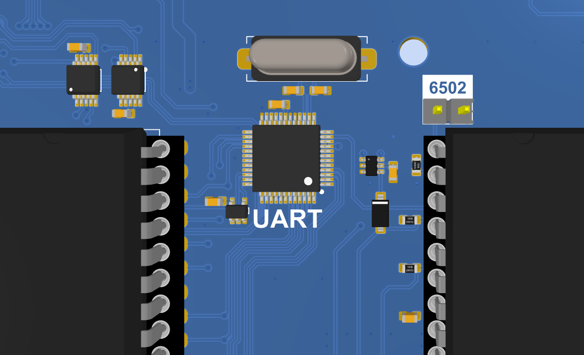
UART
One of the trad-offs Commodore did with the VIC 20 and Commodore 64 was to ditch the 6551 ACIA and bit-bang this with the 6522. This caps the usable baud rate and speed considerably.
VIC NX has the ability to swap out a number of IO pins from the 6522 that are used for the serial port and connected them to a hardware UART again. This will allow for much much higher speeds.
Housekeeping
For housekeeping we use a GreenPAK from Renesas (SLG 46620). This handles a lot of the work around power and reset.
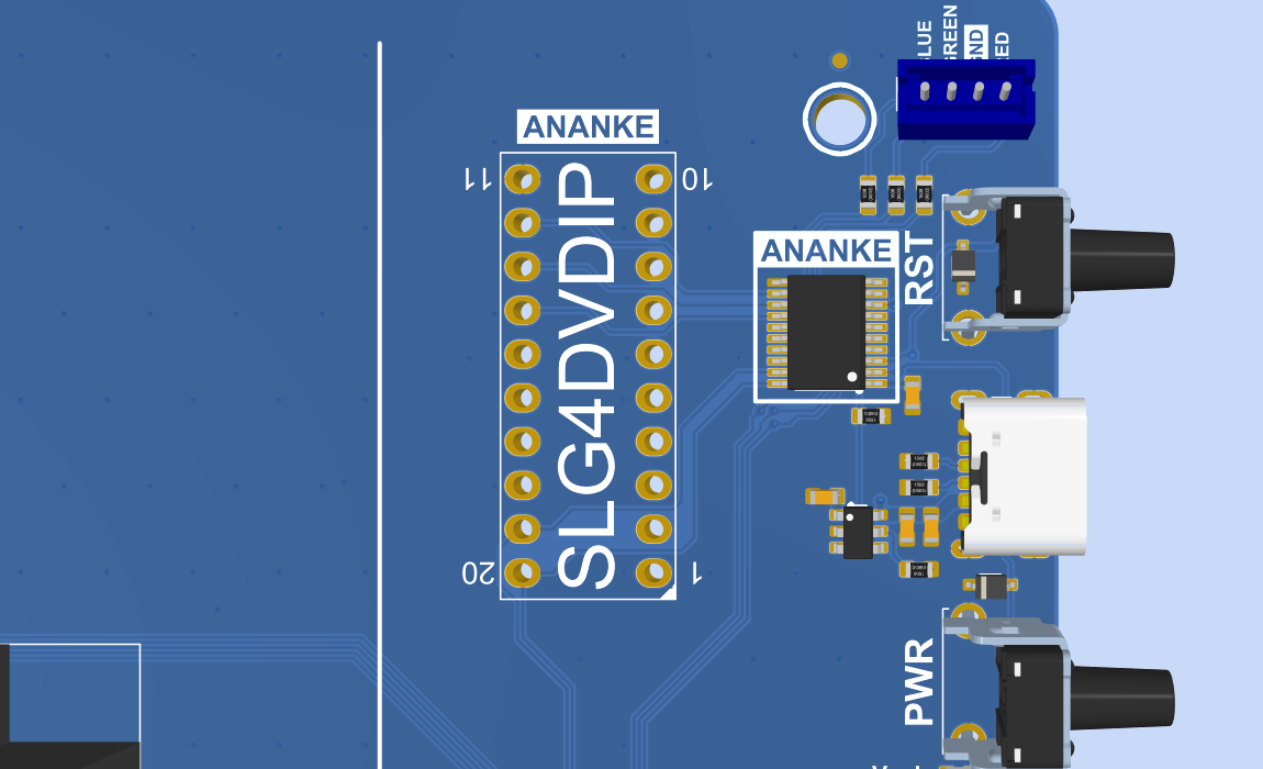
This circuit, called ANANKE handles the following work.
- Reset switch and power on reset. Controlls the overall reset of the system including the Meatloaf.
- Power on, and off, switch.
- A RGB LED that replaces the red top LED, and shows various statuses.
- Handles overcorrent during a short circuit of the 5V rail or similair. To protect the system.
CMODE is signaling to the CPLD that we are running in configuration mode. It will then swap in a special FLASH area as well as it's own SRAM.
MMODE for routing BLK6 to NLK2 and NLK7 to BLK5 for recovery mode. It is named after Mia (a wellknown person in the community) since she came up with the brilliant idea.