Table of Contents
Background
I have never understood why the logic probes went out of style. A really nice tool to have during development. Often you just want to see if there is live on the pins.
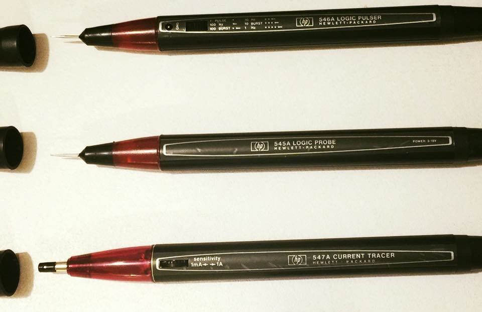
HP had the best once. Had ...

They could show basic signals as high, low and clock. HP also had a whole series of tools to also inject signals and trace currents.
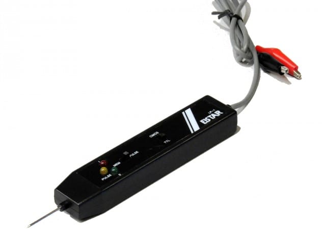
The ones that exists today is poor quality, clumsy and just ... crap.

So I decided to make my own. I have had it working for some time, but now moved into a more product development phase.
Features
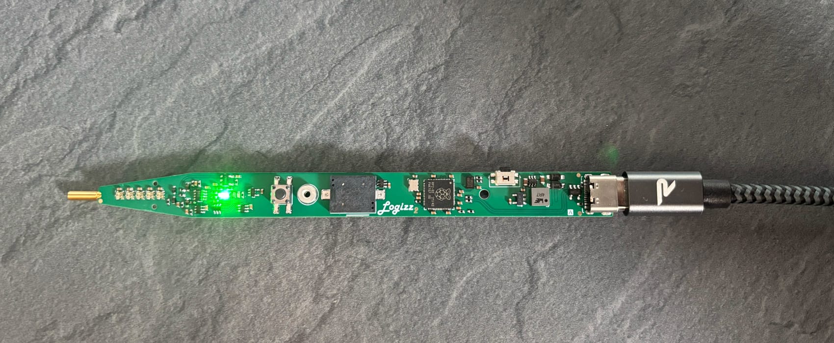
It is powered from the DUT, and this is also how it gets the reference voltage. It has two thresholds and a weak bias, so it can detect an open or floating signal.
Firmware can be updated through the USB Type-C connector.
The UI has 5 RGB LEDs that are individually addressable. There is also one button for some set-ups as well as a buzzer to audible indicate high, low etc.
It detects the following signal types;
- High, Low and HiZ. Shown as steady RED, BLUE or GREEN.
- Glitch at High or Low. Shown as High and Low, but with a YELLOW"blip".
- Clock is shown as YELLOW.
- PWM is shown as PURPLE.
- Data is shown as ORANGE.
- Analog signals is shown as a WHITE sinus wave dimming up and down.
It can detect signals between 0.8V and 5V at a frequency of up to 150MHz (pending verification).

