Table of Contents
I had an issue with the latest addition of "double tap" on reset to boot into an unexpanded VIC20. See more here.
Under certain conditions the VIC20 would freeze during boot when doing the "double tap".
How and when?
When the lower 3k was permanently switched of via the DIP switches this never happened.
If I configured the GreenPAK to never select the lower 3k regardless it also never happened.
If I always selected the 3k regardless of DIP switch, nor anything else internal to the GreenPAK, it also worked like a charm.
WTF was going on?
It was apperant that the problem was with the lower 3k. BLK1, 2, 3 was deselected and worked just as I wanted.
Part 1 - Memory testing in VIC 20
After reset is released VIC20 does some standard stuff.
RESET
    LDX #$FF                      ; set X for stack
    SEI                           ; disable interrupts
    TXS                           ; clear stack
    CLD                           ; clear decimal mode
    JSR CARTRIDGE                 ; scan for autostart ROM at $A000
    BNE BOOT                      ; if not there continue Vic startup

    JMP (LAB_A000)                ; call ROM start code

BOOT
    JSR LAB_FD8D                  ; initialise and test RAM
    JSR LAB_FD52                  ; restore default I/O vectors
    JSR LAB_FDF9                  ; initialize I/O registers
    JSR LAB_E518                  ; initialise hardware
    CLI                           ; enable interrupts

    JMP (LAB_C000)                ; execute BASIC
It checks for a cartridge, and if found, it jumps to it's starting point.
If not, it starts the boot process. First thing it clears RAM at the zero page, and page 1 and 2. It checks the rest of the RAM and sets start and top of available memory.
Below is a simplified flowchart, with the juicy bits.
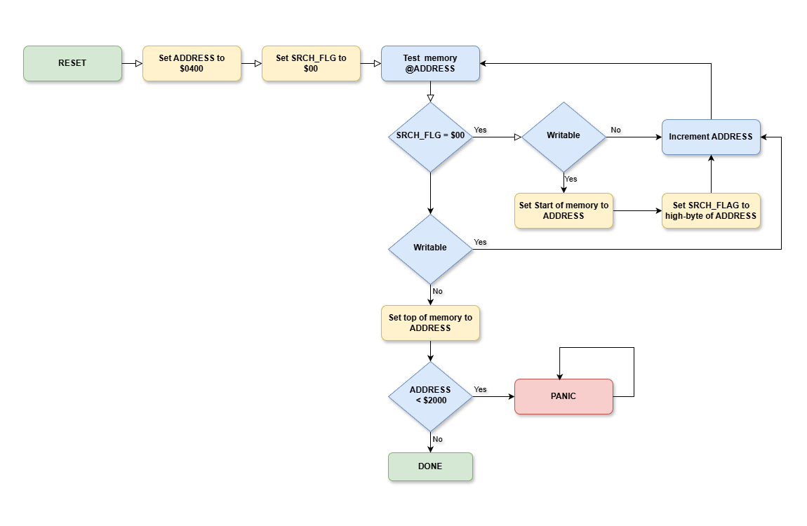
So first it starts by setting a pointer to $0400.
This is the first possible usermemory locations. This is where the lower 3k is placed. Between $0400 - $0FFF. The internal memory is between $1000 - and $1FFF, and is always there otherwise the VIC20 panics.
It also sets a flag to $00. This flag tells the loop, we will enter, if it is searching for start of memory or top of memory.
The idea is to try to write every location and during the first phase to find start of memory it will continue trying to write until it succeeds. When it finds the first writable loation this is then start of memory.
It will then flip the flag and do the opposite. Try writing to every memory location and when it finds a location that is not writable it will conclude that is the top of memory.
Part 2 - Double tap
The double tap work as follows.

Stage 1
First the reset is pulled low. This can be from the builkt in button or any oither reset button that pulls VIC20 RESET pin low.
Stage 2
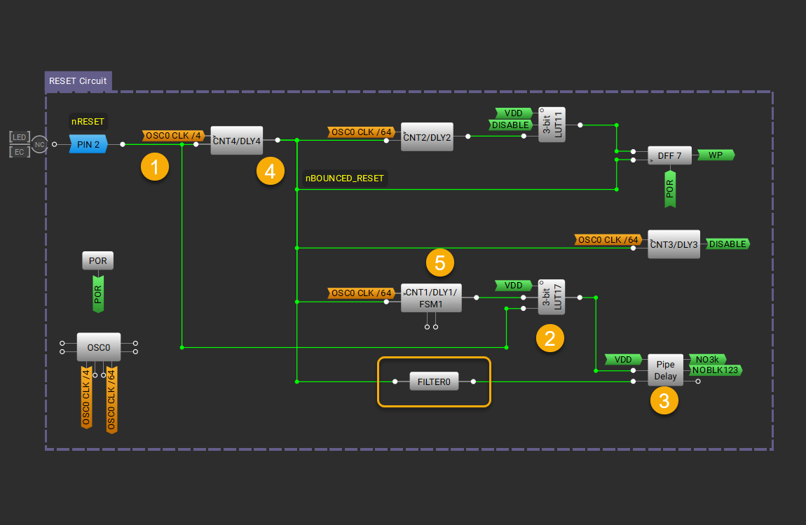
The delay line in 5, is at this time rested at a '0' output. The gate at 2 is configured is configured to let any reset signal through whenever the delay line at 5 is resting.
This is to make sure we can reset the VIC20 to full expansion, as the DIP switches say, with a quick and single reset.
Stage 3
The 16 bit (we only use 2) shift register is reset. The shiftregisters input is tied hard to VDD, or a '1'.
Any clock pulse going high (and this was unfortunately not configurable) will shift in a '1'. both NO3k and NOBLK123 is tapped from the second D-FlipFlop in this register. Which means two clkpulses, or reset puishes, is needed for the NO3K and NOBLK123 to turn high '1'.
So far so good
Stage 4
The CNT4/DLY4 is a 40ms glitch/debounce filter. Push buttons are notorious for bouncing when pressed and/or released. This bouncing can produce many '0' - '1' and/or '1' - '0' tranisations, beeing mistaken for many pushes on the reset button.
So 40ms after the reset it will go low '0', and also 40ms after reset is released it goes high '1'. This is where we start to see the problem.
Stage 5
This delay block is a one-shot timer. It will go high '1' at the first reset and stay high for 350ms. Together with the gate it will stop any further resets from reseting the pipe-delay/shift register.
The problem
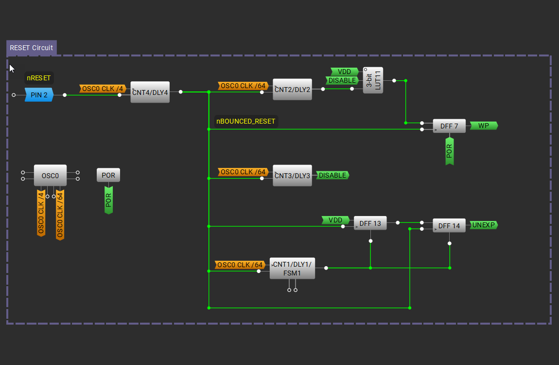
In the previous version. Which just 2 D-Type FLIP Flops for the shiftregister, the shift occured on the release of the reset, when the reset signal went high '1'.
HOWEVER
The VIC20 starts crunching as soon as the reset is released, but our logic waits for the glitch filter CNT4/DLY4 before it reacts.
40ms is almost an eternatiy even for a computer running at 1MHz. It blazes through the initial setup, checks for a cartridge clears zero page and page 1 and 2 of memory, finds memory at $0400 and sets start of memory to that, then it scans for top of memory.
Sometime in the lower 3k the logic in the GCart DCNT reacts to the release of reset, understands it is a double tap and disables the lower 3k.
Auch!
The VIC20 can't write to memory anymore and sets top of memory to somewhere between $0400 and $0FFF.
Then catastrophy strikes!
    LDY LAB_C2                    ; get test address high byte
    LDX LAB_C1                    ; get test address low byte
    CPY #$20                      ; compare with $2000, RAM should always end at or after
                                  ; $2000 even with no expansion memory as the built in RAM
                                  ; ends at $1FFF. therefore the following test should
                                  ; never branch
    BCC DEAD_END                  ; if end address < $2000 go do dead end loop

    [snipped]

DEAD_END
    JSR LAB_E5C3                  ; initialise Vic chip
    JMP DEAD_END                  ; loop forever
Any high byte of the top of memory that is below $2000 means the internal memory is bad and the VIC20 freezes and enters a dead end, looping forever.
So why did it work with the 3k disabled or forced enable?
When the lower 3k was disabled by the DIP switches or forced off the VIC20 never found a writable location in $0400 and $0FFF and the start/top of memory was legal. In the same way, when forced to be accessable the lower 3k was never top of memory and an issue.
The Fix and resource constrains
Well. The basic fix was to not count the number of times reset goes high (RESET button released) but to count the times it goes low.
Easy enough.
Then we have the GreenPAKs constraints of resources. This particular device only has 16 gates that also can be configured as D-Type Flip Flops, 5 counters/delay lines, 1 4 input gate, and a few other special types.
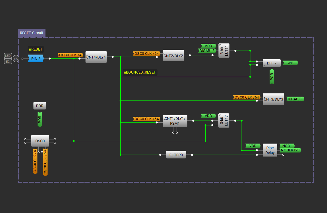
I didn't have enough left. So I rearranged the gates and turned 2 Flip Flops back into 3 input gates and used the pipe-delay or 16 stage shift register instead.
However, still missing an inverter to invert the reset going low to a clock signal to the pipe-delay/shift register going high.
Well well
But ... there was a filter over. A filter for removing fast glitches (less than 100ns). I sometimes use them for cleaning up the gated read/write signal and/or chip selects. But here I had 2 unused, of the two available!
On this bad boy you can select the polarity on the output, so basically it can be viewed as a slow inverter. The slowness doesn't matter here. But the inversion does.
So. Added. See the part enclosed in a yellow rectabgle.