Table of Contents
Every hardware project eventually teaches you the same lesson: the debug interface you bolted on as an afterthought is never quite right. The test points are in the wrong place, the UART is on a 0.1" header that shares space with a stray decoupling cap, and the JTAG pinout is whatever you remembered from the last design. By the third or fourth board you start to think seriously about standardising.
That is exactly where NetMeld Debug ONE came from.
The Problem With Ad-Hoc Debug Ports
When you are building a family of boards — or even just iterating on a single complex design — the cost of inconsistency adds up quickly. Different UART baud rate assumptions. Different JTAG connector footprints. Power rail monitoring hacked together with bodge wires to a multimeter probe. None of it is catastrophic in isolation, but collectively it means every bring-up starts from scratch and every piece of debug equipment has to be reconfigured by hand.
The NeoCore ONE is the first product to carry the NetMeld Debug ONE port, and the intent from the start was that this port would become a standardised fixture across the entire product family and any future designs where it makes sense to include it.
What the Port Provides
The NetMeld Debug ONE port is a superset of what you normally want during hardware bring-up, all on a single connector.
Power rail supervision — 8 channels
Eight analogue inputs allow voltage monitoring of up to eight independent power rails simultaneously. This is not just about knowing whether a rail is alive: the port exposes the sequencing of those rails, which matters a great deal on designs where an FPGA or processor has strict power-on ordering requirements. Watching eight rails come up in a single view, with relative timing visible, is qualitatively different from probing them one at a time with a multimeter.
GPIO — 16 channels
Sixteen GPIO lines are available for general-purpose use. In practice this covers a wide range of bring-up tasks: reading the state of configuration straps or status pins, monitoring interrupt lines, toggling reset or power-enable signals, or just confirming that a logic signal is where the schematic says it should be. Two of the lines can also be mapped to physical buttons on the advanced debug board, which is useful for driving signals interactively without needing a script or a host computer.
Two UARTs
A pair of independent UARTs covers the most common case where a device has both a primary console and a secondary diagnostic or AT-command interface. Having both available simultaneously, on the same connector, without having to decide which one to sacrifice, is a small quality-of-life improvement that pays for itself immediately.
JTAG
Full JTAG access for programming and debugging. On the advanced debug board this is presented over USB-C with the RP2350 emulating the USB VID/PID of several common JTAG dongles, meaning existing tool chains — OpenOCD configurations, FPGA programmer software, whatever you are already using — see a familiar device without any special driver installation.
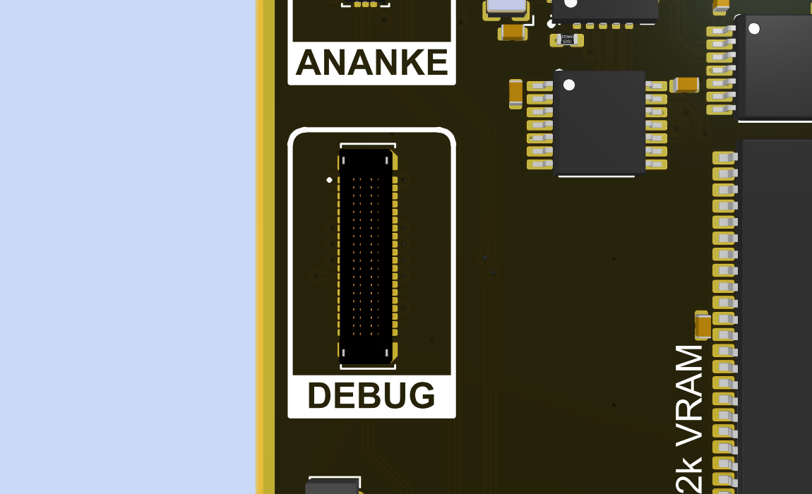
The Connector
Fitting all of this onto a connector small enough to be practical on a dense PCB required going to a board-to-board style footprint rather than the traditional debug header. The connector used is the TE Connectivity 4-2363961-0: a 40-position, double-row, 0.4 mm pitch SMT board-to-board part from TE's fine-pitch BTB series. Mated footprint on the PCB is approximately 11 mm × 3.5 mm.
That is a genuinely small footprint for 40 signals. The trade-off is that it is not hand-solderable in any practical sense, and the mating breakout board needs to be reasonably well aligned before the connectors engage. The 0.4 mm pitch does not tolerate slop.
The way I do this is to have a custom FPC between the DUT and the breakout boards.
The FPC Interconnect
The BtB connector on the DUT does not mate directly to the NetMeld board. Between the two sits a custom FPC — a flexible printed circuit with a BtB plug on the DUT end and an FFC connector on the NetMeld end. The FPC is 150 mm long and carries a ground plane on its secondary side.
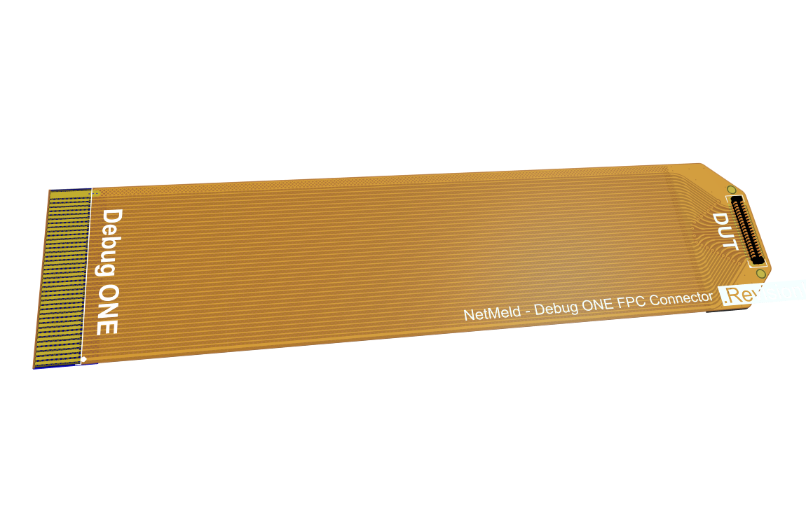
The flex serves an obvious mechanical purpose: it decouples the NetMeld board from the DUT physically, so you are not cantilevering a board-mounted instrument off a fragile 0.4 mm pitch connector under any kind of stress. But the ground plane on the reverse side is doing real electrical work too. The GPIO lines and rail monitoring signals are slow enough that the FPC is a non-issue for them. JTAG is the signal worth thinking about, and a 150 mm FPC with tightly coupled reference ground is in practice better behaved than the unterminated IDC ribbon cables that ship with most bench JTAG programmers. The geometry is controlled, the coupling to reference is consistent along the full length, and there are no flying leads picking up noise from whatever else is on the bench.
JTAG clock rate limits over the FPC are still being characterised, so no hard number is published yet. In the meantime, the conservative approach is to stay at or below whatever the target device's JTAG interface comfortably handles at the conservative end of its range — which for most devices is well within what the FPC can support.
Two Breakout Boards
The port is passive on the device side — it just exposes signals. The intelligence lives in whichever breakout board you attach.
NetMeld — Debug ONE Passive
The passive breakout is the fast option for lab work. It breaks out the JTAG and UART signals to standard connectors suitable for a logic analyser or oscilloscope probe, and provides LED indicators for all 16 GPIO lines. No firmware, no configuration, no USB enumeration to wait for. Attach it, power the device, and start probing. It is particularly useful in the early stages of bring-up when you are not yet confident that anything on the device is working and you want visibility without any dependency on the debug board itself being functional.
NetMeld — Debug ONE Active
The active breakout is a standalone instrument built around the RP2350. It connects to a host over a single USB-C cable and presents the two UARTs and JTAG over that connection. The UART and JTAG is handled by a FTDI chip found in plenty of programmers. The RP2350 can simulate different VID/PID and other enumeration data for the FTDI chip. Suported VID/PID profiles cover several common FPGA and embedded debug tool chains, so you can point your existing software at it without any special configuration.
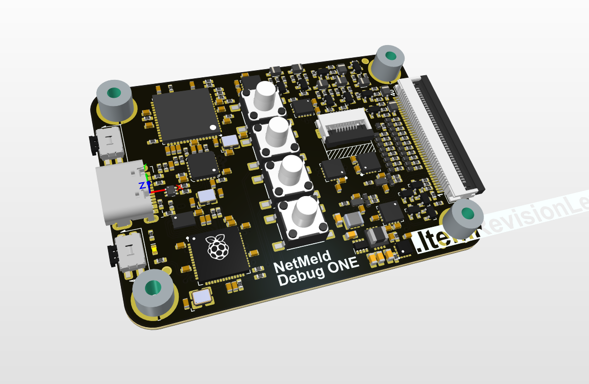
The board includes a 3.5" LCD display with a UI built around a small set of physical buttons. The display provides:
- GPIO state — all 16 lines visualised simultaneously, showing current logic level, and raising/falling.
- Rail voltage — live voltage readings on all eight monitored rails
- Rail sequencing — a timing view of how the rails came up relative to each other, so you can verify that your power sequence matches the device datasheet requirements without needing a logic analyser running in the background
Two of the buttons are user-assignable and can be mapped to any of the 16 GPIO outputs, which lets you drive reset, power-enable, or any other control signal from the front panel without needing to run a command on the host.
Where This Fits
The NetMeld Debug ONE port is not a replacement for a full-featured JTAG debugger or a bench power supply with logging. It is designed to occupy the gap between "a few test points and a UART header" and "a full rack of test equipment." For typical firmware bring-up, power sequencing verification, and interactive GPIO testing, having everything on one small connector with a consistent interface across board revisions removes a significant amount of friction.
NeoCore ONE is the first to carry it. It will not be the last.